You are here: Building the Model: General Elements > Path Networks > Path Networks Editor
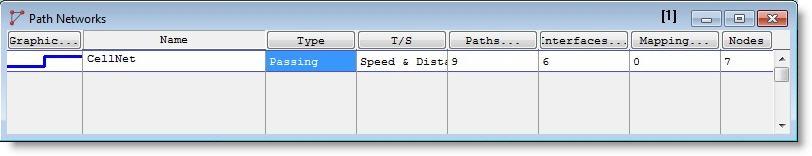
The Path Networks Editor consists of an edit table with fields for defining basic information about each network, such as the network name, the type of network (Non-Passing or Passing), and the basis for movement along the network (Speed and Distance or Time). Clicking on the appropriate heading button will bring up a table for defining nodes, path segments, and location node interfaces.
The following explains each field of the Path Networks edit table.
Graphic For passing or non-passing path networks, this button displays the Path Color dialog, which allows you to define the color of the path network. Click on the heading button or double click in this field to bring up the graphic dialog. Both dialogs allow you to specify whether or not the network will be visible at run time.
Name A name that identifies the path network. For more information about valid names, see Names.
Type Set this field to Non-Passing if you want entities and resources to queue behind one another on the path network. If a path is Non-Passing, entities may not pass each other, even if an entity is traveling at a faster speed than the one in front of it. Set this field to Passing if you want entities or resources to pass each other on the path network.
A "Crane" option is also available, which is described in more detail in the section "Crane Systems" on page 263.
T/S Set to either Time or Speed and Distance as the basis for measuring movement along the network. See the discussion on Automatic Time and Distance Calculation later in this section for more information.
Paths The number of path segments in the network. Clicking on the heading button opens the Path Segment edit table where the user may define the network's node to node connections. The Path Segment edit table is covered in more detail later in this section.
Interfaces The number of location-node interfaces in the path network. If an entity will be picked up or dropped off at a particular location by a resource, that location must connect to a node through a location-node interface. Clicking on the heading button opens the Interfaces edit table where the user may define nodes that connect to processing locations. The Interfaces edit table is covered in more detail later in this section.
Mapping The number of entries in the Mapping edit table. Clicking on the heading button opens the Mapping edit table where the user may map destinations to particular branches of the network. (The Mapping edit table is covered in more detail later in this section.)
Nodes The number of nodes defined in the Nodes edit table. Nodes are created automatically when graphically defining path segments. Click on this heading button to open the Node edit table, which may be used to define nodes manually or set Node Limits on one or more nodes. Nodes may also be used to control a resource's behavior through node logic or search routines such as work and park searches (see Resources). The Nodes edit table is covered in more detail later in this section.
How to create a path network graphically:
1. Set the default time and distance values per grid unit from the Grid dialog box.
2. Choose Path Networks... from the Build menu.
3. Enter the name of the network in the Path Networks edit table.
4. Select either Passing or Non-passing as the network type.
5. Select either Speed and Distance or Time as the travel basis.
6. Click on the Paths... heading button to open the Path Segment edit table.
7. Lay out the network using the mouse buttons as described below.
1. Left click to create a node and begin a path segment.
2. Additional left clicks produce path joints.
3. A right click ends the segment and creates a new node.
• Left click on that node.
• Right click on an existing joint.
1. Right-click anywhere on a path segment.
2. Select Add Node from the menu.
3. Drag the joint to the desired position.
Please note
If you hold down the CTRL key and move the cursor over a path segment or joint, the Add/Delete joint cursor will appear. From here, left click to add or delete a joint.
• Left click on that path.
How to create additional nodes or move existing nodes:
1. Click on the Nodes heading button in the Path Networks edit table.
2. Click the left mouse button to create a node both on the layout and in the Nodes edit table.
3. Drag an existing node to move that node.
1. Click on the Paths heading button in the Path Networks edit table.
2. Left click on any path segment and drag to the desired position. The entire network will move.